

The VAIO P’s display is one of the main reasons we chose to rebuild the machine. The 8-inch, 1600 x 768 panel gives the laptop its unusual long, narrow shape. Replacing it with a generic HDMI screen would lose much of the point.
Keeping it means solving an interface mismatch: the Raspberry Pi CM5 does not directly produce the LVDS signal expected by the Sony panel.
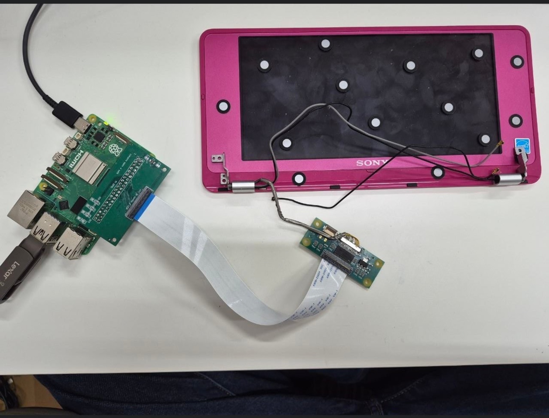
Signal path
Our display path is Raspberry Pi DPI to LVDS. The Pi exposes parallel RGB through GPIO, and the Koyomi LVDS board converts it into the signal expected by the VAIO P panel.
Project Koyomi matters because it was built for this exact problem, not for a vaguely similar laptop screen.
Read the LVDS display bring-up guide, the Koyomi LVDS board build log, and the Koyomi LVDS HAT project page for related background.
The Koyomi project page keeps the KiCad source, release status, fabrication evidence, and exact Sony panel target together. We want to document our board with the same level of specificity as it develops.
Connectors
On the Raspberry Pi side, the original Koyomi HAT uses the 40-pin GPIO header. The Samtec HLE-120-02 socket is an important physical detail: this design needs a real bottom-entry connector, not just a convenient footprint in KiCad.
On the panel side, Koyomi uses an I-PEX 30-pin CABLINE-SS connector. This is where the display cable plugs in.
Keep the Sony cable
We are keeping the original Sony display harness. It is not a generic straight-through cable. It remaps pins between the I-PEX connector and the panel.
That matters because a wrong pin mapping could damage the LCD. Before the panel is powered, the wiring and rails should be checked with a multimeter.
Power rails
One easy-to-miss detail is that the panel logic uses 2.5 V, not the Pi’s familiar 3.3 V rail. That makes first power-up a measured bench test, not a plug-it-in-and-see moment.
The LCD board needs careful power sequencing and verification before first light:
- confirm panel connector orientation
- verify ground pins
- verify the 2.5 V logic rail
- verify backlight wiring
- check for shorts before connecting the panel
- test the display path before integrating the full CM5 carrier
First-light goal
The first meaningful milestone is a stable image on the original display, with safe backlight control and the right panel voltages. Only after that works does the LCD board earn a place inside the laptop.
Once that works, the LCD board can become part of the larger CM5 carrier-board plan.